
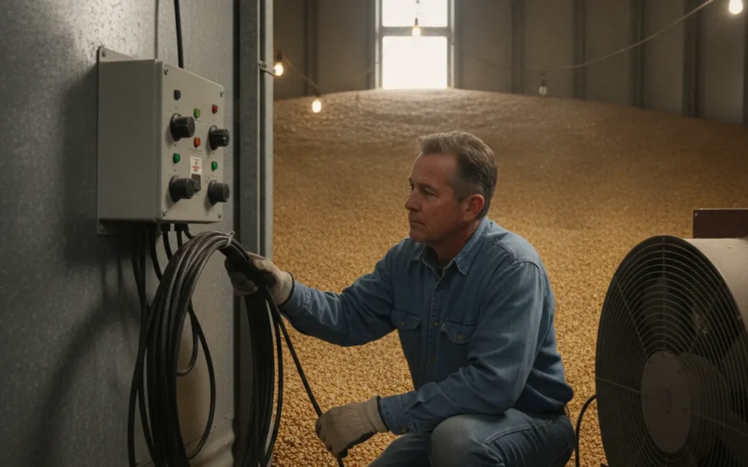
Grain fan controller sensor calibration matters because fan decisions depend on readings that represent conditions inside and around a bin. Before changing a setting or replacing a sensor, check what the sensor measures, where it is installed, and whether its reading agrees with a suitable reference. A careful comparison can help separate a sensor problem from ordinary differences in location, grain conditions, or timing.
What does a grain fan controller sensor measure?
A monitoring system may use temperature, humidity, or other sensor information to help an operator understand storage conditions. A controller may use some of those readings when determining whether a fan should run. The sensors, locations, display labels, and control logic vary by system. Start with the manual for the model you own rather than assuming that a procedure for another controller applies.
Identify each sensor before comparing readings. A probe embedded in grain, an outdoor air sensor, and a sensor near a fan can show different conditions without any of them being defective. Grain temperature can vary by depth and location, and outside air can change quickly. A comparison is meaningful only when you know which measurement each value represents.
It also helps to distinguish grain moisture from air humidity. They are related to storage decisions but are not interchangeable measurements. For an overview of temperature monitoring equipment, see grain bin monitoring with Grain Temp Guard. Farm Shop MFG also has a moisture sensor guide for grain storage that covers a related but separate measurement question.
What should you check before calling a reading inaccurate?
Begin with the display and the conditions around the sensor. Write down the value, its units, the channel or sensor name, the time, and whether the fan is operating. Check whether the value is temperature, relative humidity, or another measurement. A mistaken channel or unit can look like a failed sensor even when the equipment is reading as configured.
- Sensor identity: Confirm which probe or channel the display is showing. If the controller has several inputs, check the labels and the system manual.
- Location: Record whether the sensor is in grain, in an air space, near the fan, or outdoors. Do not expect unlike locations to match.
- Units and settings: Confirm that the controller and your reference use the same temperature scale and the same type of humidity value.
- Timing: Take paired readings close together. Conditions can change, especially for outside air or when a fan has recently started or stopped.
- Physical condition: Look for a shifted probe, visible damage, blocked openings, moisture, corrosion, or a loose cable connection.
- Operating state: Note fan operation and recent changes to the grain, airflow, power, or controller settings.
Follow the manufacturer’s safety instructions when inspecting equipment. Disconnect power before examining wiring if the manual calls for it, and do not open sealed components or touch electrical connections unless you are qualified and the instructions permit the work. A visual check should not turn into an unapproved repair.
Do not call a sensor inaccurate based on one difference. The reference instrument could be inaccurate, the measurements could be from separate locations, or one device may not have stabilized. Repeat the comparison under consistent conditions. If the difference disappears or changes direction, the cause may be variation or measurement technique rather than a fixed sensor offset.
How can you compare a controller reading with a reference?
Choose a reference instrument intended to measure the same quantity and suitable for the conditions you are checking. Review its instructions and stated accuracy. A handheld instrument measuring room air is not a like-for-like reference for a probe buried in grain. Whenever practical and safe, compare as close as possible to the controller sensor’s measurement point without pulling, shifting, or otherwise changing the installed probe.
- Write down the question. Decide whether you are checking temperature, relative humidity, or another displayed value. Make sure you know which sensor and channel are involved.
- Check the reference. Confirm the instrument is in usable condition, set to the right measurement and units, and suitable for the range you expect. Follow its instructions for placement and use.
- Match location and timing. Put the reference at the closest safe comparable point. Record the controller value and reference value at nearly the same time.
- Allow both readings to settle. Use the stabilization guidance supplied with each instrument. Avoid recording one value while a device is still responding to a move or sudden environmental change.
- Repeat paired observations. Take multiple readings using the same method. Record the values, time, fan state, and any conditions that might explain a changing result.
- Compare with documentation. Check the controller’s stated tolerance and calibration procedure. Do not assume that one universal difference is acceptable for every sensor.
A useful comparison is repeatable. If the controller is consistently higher or lower than a trusted reference at a comparable point, that pattern is more informative than a single mismatch. If readings move around, first investigate changing conditions, placement, connections, or communication. If the reference itself has no known accuracy, the comparison may show that two devices disagree, but it cannot establish which one is correct.
Some systems include a documented calibration function; other sensors are checked, replaced, or serviced rather than adjusted in the field. Use only the procedure specified for your controller. Do not enter an offset simply to make the display match an informal reading. A change can affect fan decisions, and it may conceal a placement or equipment issue.
Research on sensor-array calibration can involve methods specific to the sensors and quantities being measured. For example, the U.S. Environmental Protection Agency’s HERO record describes research on calibration for a sensor array used for gas concentration estimation: EPA HERO sensor-array calibration research. That is not a grain controller calibration procedure; for a grain system, follow its own manufacturer’s documentation.
How do common checks compare?
| Check | What it may reveal | What it cannot establish by itself | Useful next step |
|---|---|---|---|
| Display, channel, and units | Wrong sensor selection, scale, or configuration | Whether the sensing element measures accurately | Confirm the labels and settings against the manual |
| Visual inspection | Damage, obstruction, shifted placement, or a loose connection | The exact amount of measurement error | Document the condition and follow approved safety steps |
| One reference reading | A difference at one time and place | Which instrument is wrong or whether the difference repeats | Verify comparable placement and repeat the paired check |
| Repeated paired readings | A stable offset, changing conditions, or intermittent behavior | Whether an adjustment is permitted | Compare the pattern with manufacturer tolerances |
| Manufacturer service check | Equipment-specific assessment using approved procedures | How the sensor will perform after later changes | Keep the service record and monitor the same channel |
What patterns suggest a sensor or installation issue?
A display that is fixed, implausible, blank, or repeatedly different from a suitable reference deserves investigation. A sudden change that does not fit other observations also merits a closer look. The pattern provides clues, but it is not a diagnosis on its own.
As a practical example, one bin sensor seems warmer than a handheld reference. Before assuming calibration is needed, check whether the reference was placed at the same depth and in similar grain, whether both readings were taken close together, and whether either device had time to settle. If they were measured in different parts of the bin, the mismatch may reflect conditions at those locations. If repeated, comparable measurements continue to show a similar difference, record both sets of values and check the model’s tolerance. If the difference changes substantially from one check to the next, investigate timing, placement, connections, or intermittent behavior before treating it as a fixed offset. The example does not establish an acceptable difference; the equipment documentation and a suitable reference must guide that decision.
- A steady difference: If paired measurements at a comparable point repeatedly show a similar gap, check the reference’s suitability and accuracy, then consult the controller’s stated tolerance.
- A jumping value: If the display changes sharply or intermittently, inspect the approved accessible parts of the sensor path and note whether power, a cable, or communication issue may be involved.
- A stuck value: If a channel never changes as conditions change, verify that the display is live and assigned to the expected sensor before concluding that the probe has failed.
- A mismatch between sensors: First ask whether they are intended to measure comparable conditions. A probe in grain should not be expected to match outdoor air.
- A difference after maintenance: Note whether the probe, cable, controller setting, or power supply was recently changed. A before-and-after record can help narrow the question.
For a broader look at sensor placement and monitoring needs, review this guide to grain bin sensors for corn storage. When comparing air conditions with grain conditions, keep the distinction clear. A page on why grain-bin humidity monitoring matters discusses humidity as one part of storage monitoring, not a substitute for checking a temperature sensor.
How can you avoid confusing sensor readings with fan decisions?
A controller’s sensor value is only one part of the operating picture. Whether a fan should run depends on the equipment’s logic and settings as well as the conditions being measured. Do not disable protections or change operating thresholds just to make two readings appear to agree. First verify the sensor identity, the comparison method, and the controller instructions.
It can help to separate two questions in your notes: “Is this reading credible?” and “Should the fan run under these conditions?” The first is a measurement check. The second is an operating decision that depends on the system and grain-management plan. A credible sensor reading does not by itself confirm that a particular operating setting is appropriate.
If you are reviewing how airflow and drying differ, see grain drying versus aeration. For information about an automated control system, see EndZone fan controller details. Product pages can help identify equipment features, but your controller’s own documentation should guide any calibration or setting changes.
How should you keep a useful calibration record?
A brief log makes it easier to identify a recurring discrepancy and to explain it to a service provider. Record enough context that someone else could understand how the comparison was made. A difference written without the original values, location, or time is difficult to interpret.
For each check, include:
- Date and time of the paired readings.
- Controller make or model, if available, and sensor or channel identification.
- Sensor location and what it is intended to measure.
- Controller value, reference value, and the units for each.
- Reference instrument identification and any relevant accuracy information from its documentation.
- Fan status and recent operation, along with relevant changes in the bin or surrounding conditions.
- Visible condition of the sensor, cable, or accessible connection, and any maintenance or setting changes.
- The manual section or service advice used to decide the next step.
Keep the original measurements as well as any calculated difference. For example, a log entry might say that at 9:15 a.m. sensor channel two showed a certain temperature, a suitable reference showed another value at a comparable location, and both were checked again after they settled. The important part is to write down what was actually observed, not to create a false sense of precision from an estimate.
Establish a baseline after installation or a verified service check, then repeat later checks in a similar way. If the probe is moved or a cable is replaced, mark that change clearly; comparisons from before and after may not represent the same conditions. The record can also stop repeated adjustment attempts based on one unusual display reading.
What is a practical troubleshooting sequence?
When a controller reading raises concern, use a step-by-step sequence that starts with the least disruptive checks and leaves equipment-specific changes to the documented procedure.
- Pause before changing settings. Note the current display and controller state so you have a baseline. Avoid changing thresholds as a test unless the manual directs you to do so.
- Confirm the channel. Make sure the displayed value belongs to the sensor you intend to check and confirm its expected location and measurement.
- Check the simple causes. Verify units, labels, sensor placement, and visible condition. Note any loose or damaged parts without undertaking unsafe repairs.
- Use a comparable reference. Follow both devices’ directions and collect repeated paired values in stable, comparable conditions.
- Review the evidence. Consider whether the mismatch is consistent, intermittent, or limited to a particular location or operating state.
- Follow the controller procedure. Use the stated tolerance, calibration instructions, and service path for that specific model.
- Record the outcome. Note what was checked, any approved adjustment or service, and the readings afterward.
This order helps avoid replacing a working sensor because of a unit error or adjusting a controller to compensate for a misplaced probe. If the system’s instructions are missing or unclear, stop before making a change and ask the manufacturer or a qualified technician for model-specific guidance.
When should you seek service?
Contact the equipment manufacturer or a qualified technician when the display remains unstable, a sensor or cable is visibly damaged, wiring or power is suspect, or repeated comparable checks fall outside the manufacturer’s stated tolerance. Seek assistance if the calibration process is unclear or requires opening a sealed component. Electrical diagnosis and sensor replacement may require tools or training beyond a routine visual check.
When requesting help, share the controller model, channel, sensor location, paired readings, reference instrument, and relevant operating conditions. Include a photo of the installation only if it can be taken safely. This gives the person helping you a clearer basis for deciding whether the next step is a settings check, sensor inspection, or service evaluation.
Farm Shop MFG provides product information and resources for grain monitoring and farm equipment. You can also review the Grain Temp Guard monitoring system and related product details when identifying the equipment under consideration. For product-specific questions, use the contact route rather than assuming a procedure for another controller will apply.
What is the practical next step?
First identify the sensor and the conditions it is designed to measure. Then inspect its installation, compare it with an appropriate reference under consistent conditions, and record repeated results. Use the controller’s own tolerance and procedures to decide whether the system needs adjustment, repair, or further evaluation. A fair comparison and a clear record are more useful than changing a setting to force readings to match.
Contact Farm Shop MFG with a product question
Reliable fan decisions start with measurements you understand and equipment-specific guidance when readings do not agree.